Scan QR code
Attention to Lioncel
 Return
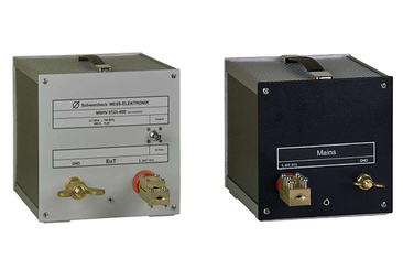
NNHV 8123-400 series asymmetric single-channel artificial power network (AMN) is mainly used to measure the electromagnetic interference of shielded cables in accordance with CISPR 25 ed4 or BMW GS 95025-1. The frequency range is 0.1-150 MHz. NNHV 8123-400 can also be used for large current injection (BCI) testing. At this time, a 50 ohm load needs to be terminated, and its impedance characteristic is 5μH || 50Ω.
The high-voltage LISN can be placed in the high-voltage shield HVSE8600 when designed, and two NNHV 8123-400 are used to measure HV+ and HV- respectively. The test object needs to be connected to the front panel, the power supply is connected to the rear panel, and the shielding layer is directly connected to the HVSE8600 shell.
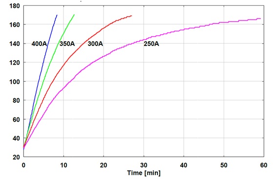
NNHV8123-400 can allow the measured object to work continuously at a continuous current of 250A, and the short-term current can reach 500A.
|
Frequency Range |
0.1 – 150 MHz |
|
Maximum continuous current |
250A |
|
Maximum short-time current |
500A |
|
Maximum voltage (DC) |
1000V |
|
Maximum voltage (AC 50/60Hz) |
700 Vrms |
|
Maximum voltage (AC 400Hz) |
300 Vrms |
|
impedance |
(5 μH) || 50 Ω(+/- 10%) |
|
DC resistance power supply-EUT |
<1.3mΩ |
|
Impedance (AC 50/60Hz) |
2.0mΩ |
|
Impedance (AC 400Hz) |
12.6mΩ |
|
EUT interface |
Wing terminal |
|
Measurement output interface |
N type (female) |
|
size |
220 x 225 x 260 mm |
|
weight |
6.0kg |
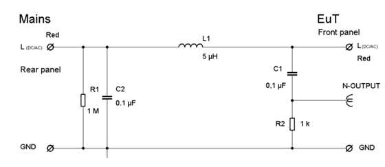
Simplified circuit diagram of NNHV 8123-400:
Interference voltage test according to CISPR 25
The power supply is connected to the rear panel, and the 0.1uF capacitor on the rear is grounded. The test object is connected to the front panel, and the interference voltage generated by the test object is output to the EMI test receiver through the N-type connector for measurement.
Each line must use an independent LISN (in the shielding box HVSE 8600), the power supply line is connected to the red terminal of one LISN, and the return line of the power supply is connected to the red terminal of the other LISN. The unused measurement port must be terminated with a 50 Ω load.
All LISN radio frequency grounds must be connected to the grounding terminal. The brass grounding terminal and the shell of the shielding cover HVSE8600 are connected. When connecting the power supply line of the EUT, the insulation layer of the cable must be stripped first to ensure the shielding layer It can be in good contact with the shielding shell of HVSE8600. The standard delivery of NNHV8123 series includes locking screws and RF output cables.
Immunity test, high current injection method (BCI test):
NNHV 8123-400 can be used with suitable current injection clamps for high current injection testing.
Adequate air circulation must be ensured to prevent the LISN from overheating.
LISN cannot be covered! The upper and lower cover plates with holes cannot be covered to facilitate air circulation. The 50 ohm external termination resistor must be placed outside the HVSE 8600.
A slight smell of coating and insulating materials may appear during the first few hours of work. Be careful not to inhale the emitted gas. The smell will disappear after working at high temperature for a few hours.
During the high current injection test, due to the danger of high field strength and heating (fire risk), this type of test should only be done by qualified engineers! The corresponding safety precautions must be considered!
During the BCI test, the power injected from the EUT terminal will cause the external 50Ω load to heat up, and the appropriate load power must be selected according to the actual test requirements.
Note: The injected RF power will be output from the EuT- terminal to the N-type port without attenuation. If a receiver is connected at this time, the receiver will be damaged!
note:
Circuits in accordance with CISPR 16 have a large leakage current to the ground, so the leakage current detection function cannot be used on the power line (they will disconnect the power supply due to excessive ground current). Either a ground current safety switch is not installed on any power cord (please mark the necessary warning signs), or a 1:1 power cord isolation transformer is used.
In any case, LISN should be grounded before connecting to the power cord. Must provide accurate safety tips to LISN users.
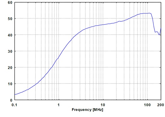
EUT terminal impedance (N-type terminal is connected to 50 ohms, power line is short-circuited)
Impedance characteristic curve
Divider ratio, EuT terminal to N connector (adapter required)

Temperature rise characteristics under continuous current

Shanghai Lioncel Electromagnetic Technology Co., Ltd(headquarters))
Tel:021-56776010 66300383
Fax:021-56775110
Email:sales@emclioncel.com
Address:2F, building 5, Changzheng Industrial Park, Lane 1225, Tongpu Road, Putuo District, Shanghai
Shenzhen Office
Tel:0755-25876847 18688776364
Fax:0755-25876847
Address:Floor 2, modern port office center, building a, film building, Guiyuan Road, Luohu District, Shenzhen
Beijing Office
Tel:13917575261
Address:Room 328, floor 3, block B, building 22, yard 26, Xihuan South Road, Beijing Economic and Technological Development Zone, Beijing