Scan QR code
Attention to Lioncel
 Return
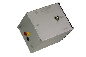
The CDN coupling and decoupling network can be used for EMI testing. Typically, the lighting products are tested according to the standard CISPR 15, and the CDN can also be tested for conducted immunity according to the standard IEC 61000-4-6.
But pay special attention: CDNE cannot be used for immunity test.
Regarding the detailed impedance characteristics, there are very clear requirements in CISPR15. The frequency range is 30~300MHz. The interference voltage is output through the BNC port of CDNE. The voltage division factor of this port is 20dB.
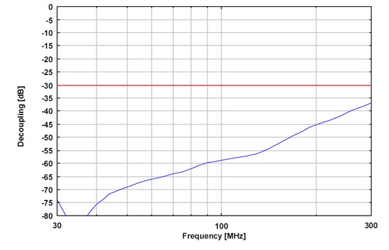
The built-in current compensation coil of CDNE can ensure at least 30dB of decoupling between EUT and AE, which can ensure that interference signals will not be brought into EUT test results.
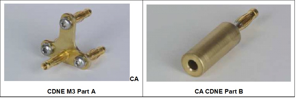
To ensure safety, all interfaces adopt safety plugs. We recommend using 4mm safety banana plugs for test connections.
In order to verify the performance of CDNE, some standards need to introduce a common mode reference point. The common mode reference point of CDNE is the short-circuit point of the unshielded cable.
In order to meet the verification of the nominal value of CDNE (ie, common mode impedance, voltage divider factor), a low-inductance, low-resistance short-circuit jumper is required.
This adapter is optional. It consists of two parts. There is a short bridge (CA CDNE M3A part) and an adapter kit (CA CDNE B part).
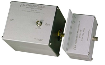
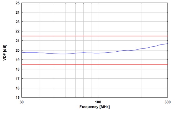
One of the most important characteristics of CDNE is the coupling attenuation between the EUT port and the BNC measurement port (other expressions: correction or voltage division factor VDF). This attenuation is recorded as each device is part of the calibration certificate. If the coupling attenuation should be calibrated in the actual emission measurement setup, a resistance of 100Ω is required to adapt the 150Ω of the CDNE to the 50Ω measurement system. For this, we provide an optional adapter SR100-6W.
There is a resistive attenuator built into the BNC output to ensure matching. According to the standard CISPR/A/944/CD Figure J2, a value greater than 6db is required. According to the design, the attenuation of the internal circuit is 9.5dB. With 10.5dB built-in attenuator, the total attenuation is 20dB. Therefore, the measurement port is very matched to 50Ω, thus replacing the external attenuator.

|
Frequency Range |
30 – 300 MHz |
|
Line type |
3- wire, unshielded |
|
EUT/AE interface |
3*4mm |
|
Output Interface |
50 Ω BNC |
|
Maximum voltage |
400 VDC , 277 VAC 50/60 Hz |
|
Maximum current |
16A |
|
Common mode impedance |
150 Ω +10 Ω/ -20 Ω |
|
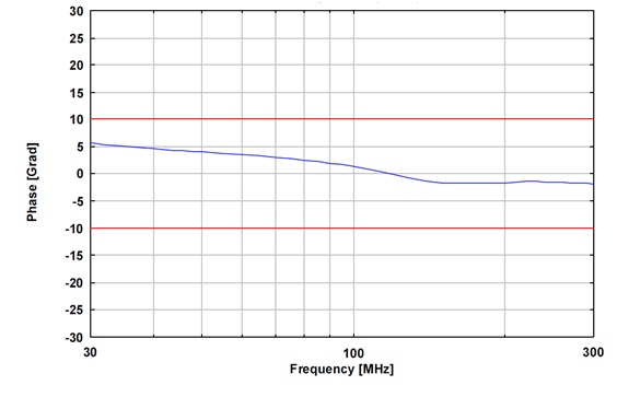
Phase angle |
0° ±25° |
|
Maximum EUT RF output voltage |
140 dBμV |
|
Maximum measurement port voltage |
5 V |
|
EUT- measurement port partial pressure coefficient |
20 dB ±1.5 dB |
|
EUT-AE decoupling capability |
>30 dB |
|
Ground terminal |
4mm terminal, M4 screw |
|
size |
104 mm x 104 mm x 127 mm |
|
weight |
850g |
|
Internal circuit diagram |
CISPR/A/944/CD, Fig. J2 |
|
Standards compliant |
CISPR 15/ EN 55015 |
EUT-AE decoupling capability
Partial pressure coefficient
Symmetrical impedance characteristics
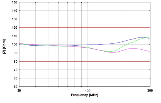
Nominal impedance characteristics

Shanghai Lioncel Electromagnetic Technology Co., Ltd(headquarters))
Tel:021-56776010 66300383
Fax:021-56775110
Email:sales@emclioncel.com
Address:2F, building 5, Changzheng Industrial Park, Lane 1225, Tongpu Road, Putuo District, Shanghai
Shenzhen Office
Tel:0755-25876847 18688776364
Fax:0755-25876847
Address:Floor 2, modern port office center, building a, film building, Guiyuan Road, Luohu District, Shenzhen
Beijing Office
Tel:13917575261
Address:Room 328, floor 3, block B, building 22, yard 26, Xihuan South Road, Beijing Economic and Technological Development Zone, Beijing