Scan QR code
Attention to Lioncel
 Return
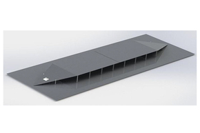
Open, asymmetrical 50W strip line, used for immunity test of auto parts. (The wooden frame structure needs to bear the ribbon line, which is not included in the delivery).
Material
aluminum
Nominal frequency range (TEM mode)
DC-220 MHz
Usable frequency range (TEM and higher modes)
DC-1000 MHz
Nominal impedance
50 Ω
SWR (typical)
<1.5 (f <220 MHz), <2 (f> 220 MHz)
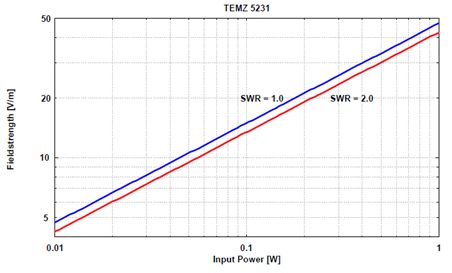
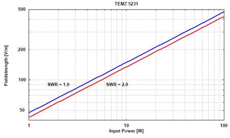
Voltage/field strength relationship
1 V = 6.67 V/m
Maximum input power
(With suitable high-power terminal)
1000W short time, 500W continuous
Inner size of strip line (width x length x height)
740 x 2500 x 150mm
External dimensions (width x length x height)
1500 x 4300 x 200mm
The asymmetric 50Ω stripline meets the requirements of ISO 11452-5 and can be used to generate TEM waves up to 220MHz. In TEM mode, the field strength distribution in the stripline is very uniform.
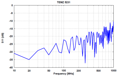
The stripline can also be used above 220MHz, in which case a higher mode does exist, which provides a position-dependent field strength characteristic. Different from the TEM mode, in the TEM mode, the field strength at the edge of the stripline is very small and increases toward the center, while the higher modes show the opposite characteristics: the field strength is small at the center of the stripline and is The edge of the shaped conductor rises to the maximum. During multimode operation, the polarization direction changes in certain areas. In TEM mode, the radiation loss and dielectric loss caused by the plastic support rod are small. Less than 1% of the incident power is reflected back into the source, which is caused by minimizing impedance mismatch.
The dielectric and radiation losses at the operating frequency of TEM are as follows: | S21 |=0.5db, loss 11%, | S21 |=1.0db, loss 21%, | S21 |=1.5db, loss 29%. In multimode operation, the loss will increase with increasing frequency. At 380MHz, only 50% of the power is output to the connector. At 800 MHz, only 25%, and at 1 MHz, only 12% of the power can be output to the connector.
For EuT positioning, it is recommended to use dielectric neutral materials, such as foam or polystyrene. The device under test (EuT) should be placed in the center of the strip line. It is recommended to record the location of the device under test as accurately as possible to achieve good reproducibility of the test.


Shanghai Lioncel Electromagnetic Technology Co., Ltd(headquarters))
Tel:021-56776010 66300383
Fax:021-56775110
Email:sales@emclioncel.com
Address:2F, building 5, Changzheng Industrial Park, Lane 1225, Tongpu Road, Putuo District, Shanghai
Shenzhen Office
Tel:0755-25876847 18688776364
Fax:0755-25876847
Address:Floor 2, modern port office center, building a, film building, Guiyuan Road, Luohu District, Shenzhen
Beijing Office
Tel:13917575261
Address:Room 328, floor 3, block B, building 22, yard 26, Xihuan South Road, Beijing Economic and Technological Development Zone, Beijing