Scan QR code
Attention to Lioncel
 Return
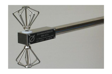
SBA9113 meets CISPR 16-1-4 for site verification above 1GHz. SBA 9113 is designed because there are no omnidirectional broadband antennas operating above 1GHz in the world. If common microwave antennas (such as logarithmic or horn antennas) are used to verify the test site, the results will be insufficient, because the directional gain antennas in these patterns do not consider the characteristics of the test site.
main feature:
SBA9113 meets CISPR 16-1-4 for site verification above 1GHz. SBA 9113 is designed because there are no omnidirectional broadband antennas operating above 1GHz in the world. If common microwave antennas (such as logarithmic or horn antennas) are used to verify the test site, the results will be insufficient, because the directional gain antennas in these patterns do not consider the characteristics of the test site.
The main purpose of the microwave biconical antenna is to evaluate the test site, measure the field strength (frequency selection) and generate a specific field strength (such as ERP or EIRP). Due to its broadband characteristics, it is not necessary to replace the antenna as frequently as a half-wave dipole antenna, thereby saving measurement time. Microwave biconical antennas allow continuous frequency sweeps to be performed across the entire frequency range. Due to its similar pattern, fixed phase center and high power handling capability to dipole antennas, SBA 9113 can replace half-wave dipole antennas in many occasions.
SBA 9113 is not suitable for very low limit radiation emission tests. Horn and logarithmic antennas are more suitable for this purpose due to their better antenna coefficients. A typical application of SBA 9113 is to determine the field strength exposure near the base station in the GSM frequency band.
|
Frequency Range |
0.5-3GHz |
|
Connector |
50 ohm; N-type female terminal |
|
Unbalanced (low loss) |
1:1 |
|
Maximum input power |
20 W |
|
Typical standing wave ratio |
1-4 |
|
Index ring |
LR=190mm |
|
Total length of antenna element |
LE =140 mm |
|
Antenna element diameter |
D = 49 mm |
|
Antenna element installation |
M4 |
|
installation |
22mm diameter tube, LH=560 mm |
|
weight |
750g |

Shanghai Lioncel Electromagnetic Technology Co., Ltd(headquarters))
Tel:021-56776010 66300383
Fax:021-56775110
Email:sales@emclioncel.com
Address:2F, building 5, Changzheng Industrial Park, Lane 1225, Tongpu Road, Putuo District, Shanghai
Shenzhen Office
Tel:0755-25876847 18688776364
Fax:0755-25876847
Address:Floor 2, modern port office center, building a, film building, Guiyuan Road, Luohu District, Shenzhen
Beijing Office
Tel:13917575261
Address:Room 328, floor 3, block B, building 22, yard 26, Xihuan South Road, Beijing Economic and Technological Development Zone, Beijing