


Scan QR code
Attention to Lioncel
 Return
Application description :
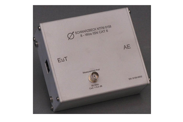
The telecommunications port of the device under test must be connected to the NTFM 8158 EUT port. NTFM 8158 provides asymmetric port termination of EUT. Auxiliary equipment (AE) that must be operated with the device under test must be connected to the AE port of NTFM 8158.
Data communication is based on differential mode voltages on pairs of wires. If the virtual zero point in the middle of the voltage is displaced compared to the reference ground, the magnitude of the displacement is called asymmetric interference voltage or common mode voltage. This voltage is separated from the BNC connector to be measured with the receiver . The nominal voltage division factor is 9.5 dB, which means that the voltage reading at the 50Ω receiver must be increased by 9.5 dB. This generates interference voltage.
LCL describes the conversion of required differential-mode data signals into unwanted common-mode signals along the transmission line. Common mode signals may be radiated and may cause interference field strength.
CISPR 22 describes the test setup in more detail. Special attention must be paid to low-induction grounding, which is suitable for radio frequency grounding. This is achieved by placing the aluminum housing of NTFM 8158 directly on the reference ground plane. The cables of the equipment under test and the cables of auxiliary equipment shall not be installed tightly or in parallel to avoid unnecessary coupling between them.
main feature:
ISN NTFM 8158 is used to measure the disturbance voltage of unshielded twisted pair (UTP) or communication ports with 2/4/6/8 wires in accordance with CISPR 22:2005 or EN 55022:2006. The equipment under test (EUT) or auxiliary equipment (AE) can be connected using RJ-45 connectors, and the pin definition conforms to EIA/TIA-T568A/B. The circuit design of NTFM 8158 is based on CISPR 22 version 5.2 Figure D.3.
The longitudinal conversion loss provided by NTFM 8158 is typically 75dB on the EUT side, allowing direct measurement of CAT6 equipment.
NTFM 8158 can not only be used for disturbance voltage measurement, but also for conducted immunity measurement according to CISPR 24 or EN 55024. In this case, a 50Ω to 150Ω impedance adapter that meets the IEC61000-4-6 standard is required as an option. This adapter can also be easily installed to NTFM 8158.
The technical indicators of NTFM 8158 are fully compliant with CISPR 22 version 5.2, and are calibrated in accordance with the method described in CISPR 16-1-2 Annex E.
|
Frequency Range |
150 kHz-30 MHz (ISN) 150 kHz-80 MHz (CDN) |
|
Types of |
T8, T4, T2-ISN, CDN |
|
Typical insertion loss (Differential mode AE-EUT port) |
<1dB (100kHz-30MHz) <2.5dB (30MHz-250MHz), see Figure 1 |
|
Decoupling (AE-EUT) |
>55 dB, see Figure 2 |
|
Longitudinal conversion loss (LCL) |
75dB@150kHz 59dB@30MHz, see Figure 3 |
|
Voltage division factor (asymmetric voltage) |
9.5 dB ± 1 dB, see Figure 4 |
|
Maximum RF voltage-EUT |
15 V |
|
Maximum RF voltage-measurement port BNC |
25 V |
|
Impedance (asymmetric) |
150Ω ± 20 Ω (≤30 MHz), see Figure 5 150 Ω + 60 Ω/ -45 Ω ,>30 MHz |
|
Common mode phase angle |
0° ± 20° |
|
Connector (AE, EUT) |
RJ-45 (8P8C) |
|
Measurement port |
BNC(female) 50Ω |
|
Crosstalk PSELFEXT typical value |
>66dB (150kHz-1MHz) >46dB (10MHz) >38dB (30MHz) |
|
parts:
Video playback:

Shanghai Lioncel Electromagnetic Technology Co., Ltd
CONTACT US:
Shanghai Lioncel Electromagnetic Technology Co., Ltd(headquarters)) Tel:021-56776010 66300383 Fax:021-56775110 Email:sales@emclioncel.com Address:2F, building 5, Changzheng Industrial Park, Lane 1225, Tongpu Road, Putuo District, Shanghai Shenzhen Office Tel:0755-25876847 18688776364 Fax:0755-25876847 Address:Floor 2, modern port office center, building a, film building, Guiyuan Road, Luohu District, Shenzhen Beijing Office Tel:13917575261 Address:Room 328, floor 3, block B, building 22, yard 26, Xihuan South Road, Beijing Economic and Technological Development Zone, Beijing 
Scan QR code
Attention to Lioncel Online store links:
Related website links:http://www.emclioncel.com/index.asp
|

