 Return
Broadband Artificial Network (BAN) is used in the automotive industry to directly inject radio frequency power into signal or power lines. This method is called "direct power injection."
The BAN provides good isolation between the AE port and the EUT port. Therefore, the injected RF signal mainly points to the EUT port. From the EUT port, the BAN provides a standard minimum impedance, and the RF signal from the amplifier is loaded by this impedance. Higher current BANs require larger ferrites, which have lower impedance and poorer decoupling. Therefore, BAN8530 can only be used in the range of 8A-30A. For the current less than 8A, it is not suitable to use BAN 8530.
The basic circuit is an L/C low-pass filter with a wideband monolithic ceramic capacitor on the AE end, and the inductance is formed by five toroidal coils in series.
The choice of BAN depends on the maximum current and signal transmission rate. BAN8530 specifies the current between 8A-30A.
The test arrangement and measurement methods refer to manufacturer standards such as ISO 11452-7 or DaimlerChrysler DC-10614 (2005-03).
BAN must be connected in series with the device under test (DUT), so a 4mm socket is used. For higher currents, a hook-type cable lug is used because its contact resistance is low and the heat dissipation is small. The red AE connector in ISO 11452-7 is called "terminal 2" and is connected to the power supply of our auxiliary equipment.
The black terminal on the AE side is connected to the reference ground. It can be used to measure the electrical characteristics of the BAN or as an additional ground connection. The ground connection of the BAN has been provided by the metal plate of the BAN8530 base.
The BNC connector can be used to inject radio frequency signals from the generator/amplifier into the DUT. In the above standards, the BNC connector is also called "terminal 3".
According to the standard, a DC blocking capacitor must be used. It must be connected to the BNC jack and provide isolation between the DC on-board voltage and the RF injection device, so as to avoid the possibility of damaging the connected measuring equipment through the on-board voltage DC. Choose a suitable DC blocking capacitor, it is "DC Block 500".
For those less than 8A, it is recommended to use BAN8508. BANs with other currents or transmission rates can be provided on request.
The solder joint of the EUT power cord is defined as the reference surface for measuring the impedance of the BAN8530.
Safety advice:
BAN 8530 has an open frame design, so it has no protection against accidental contact. Depending on the working voltage, dangerous voltage may appear. Therefore, conductive objects must not be placed on or near the ban. Any user must understand the possible dangers. The equipment must be set up in a closed environment to prevent accidental contact with wires.
If the BAN runs for a long time under high current, the coil will heat up, and only technicians can use the BAN. In addition, the safety standards of the country using the BAN must be observed.
model
BAN 8530
Frequency Range
250 kHz – 500 MHz
Nominal rated range
8 A – 30 A
Line type
Single line
DUT/AE interface
6mm terminal, 4mm banana jack
Maximum linear voltage
100 V DC
Maximum linear current
30 A DC
port
50 Ω BNC
RF maximum output power
5 W
Decoupling (EuT / BNC to AE end)
250 kHz – 500 MHz , >20 dB
impedance
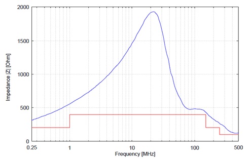
250 kHz – 1 MHz, >200 Ω
1 MHz – 150 MHz, >400 Ω
model
BAN 8508
Frequency Range
250KHz~500MHz
Nominal rated range
2A~8A
DUT/AE interface
6mm terminal, 4mm banana jack
Maximum linear voltage
100V DC
Maximum linear current
8A DC
port
BNC
RF maximum output power
5W
Decoupling (EuT / BNC to AE end)
0.25 MHz to 1 MHz ,>20 dB
1 MHz to 500 MHz ,>35 dB
impedance
0.25 MHz to 0.5 MHz ,>200 Ω
0.50 MHz to 250 MHz ,>500 Ω
250 MHz to 500 MHz ,>200 Ω
Dimensions W x H x D
128 mm x 54 mm x 41 mm
weight
About 160 g
standard
DIN ISO 11452-7: 2002-07
DC-10614 : 2005-03
Attenuation from BNC (Eut) to AE:
impedance:

