 Return
|
Frequency Range |
20 kHz – 10 MHz |
|
Test output |
50 Ω , BNC(f) |
|
Ambient temperature |
-10°… +60°C |
|
Diameter of test sphere / head |
210 mm |
|
Diameter of the rod fixing clip |
38 – 50 mm |
|
weight |
About 310 g |
Measurement procedure:
The Van der Hoofden test head consists of three parts: a conductive sphere with a diameter of 210 mm, a connecting cable with a length of 300 mm, and a protection network for the EMI receiver.
The test head has a 3/8” internal thread, which can be easily installed on a height-adjustable tripod. The protection network is fixed on the telescopic pole of the tripod by a mounting fixture, and is connected to the test head through a 300mm cable. There is a 4mm banana plug, and the clamp with a protective net must be fixed to the telescopic rod under the head.
AM 9144 with the option "Very Short" is a perfect stand system, allowing a height setting range of 0.8-1.4 m. According to IEC62493, the minimum required height is 0.8 m, and AM 9144 allows continuous adjustment of the height to 1.4 m in a telescopic manner. Adding extension rods with fixed lengths of 0.6m and 1.2m can continuously adjust the range from 0.8m to 3.2m.
The EMI receiver measures a voltage of 50Ω and must be connected to the BNC connector on the bracket clip. In order to determine whether the luminaire meets the standard, the measured voltage must be converted into an induced current density. The measured density must be expressed in allowable density and must be summed. The result is a factor called F. If F does not exceed 0.85, the DUT meets the requirements. These calculations are easily integrated into Messbase software. The following receiver types can be used to perform measurements: FCKL 1528, FMLK 1518, FCLE 1535. If a different type of receiver is used, or if Messbase software is not available, the "Van der Hoofdenest" program can be used to calculate F from the measured voltage.
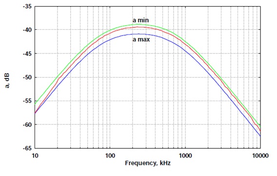
Typical transmission of protection circuits, including tolerance limits of calibration measuring devices.
Output diagram of protection circuit

According to IEC 62493, use SchwarzbeckMessbase software for testing. According to IEC 62493, the test parameters of the receiver are as follows:
1. BandA (20kHz-150kHz): peak detector, 220 Hz step size, direct input, low distortion, test time 100 ms, bandwidth 200 Hz.
2. Band B (150 kHz-10 MHz): peak detector, 10 kHz step size, direct input, low distortion, test time 20 ms, bandwidth 9 kHz.
During the test, do not call any antenna factor file to the receiver, measure band A and band B respectively, and get the voltage measurement results. Note the possible source of error: Since each band must use a different measurement time, the band A and band B must be measured separately.
After the measurement is completed and saved, the factor F can be calculated. To perform calculations, the measured values at positions 1 and 2 must be loaded into the Messbase software. It does not matter whether band A or band B is loaded into position 1 or 2.
之后,必须单击任务栏上的按钮。在计算过程中,将波段A和波段B测量值合并,计算因子F并将其输入最后一条注释行。最后保存测量结果。
用独立软件计算F因子
如果Messbase软件不可用或使用了不同的仪表,则可以使用可下载软件“Van der Hoofden Test”。它允许根据测量的电压计算F。数据必须具有以下格式:
Frequency1,Level1
... ...
... ...
FrequencyN,LevelN
频率单位是kHz,电平单位是dBμV。
单击按钮“File” ,选择电压文件,单击“calculate” ,就能得到F因子值:

特别是对于R&S的测量接收机,需要专用软件Van_der_Hoofden_Test_RSFormat.exe. 包括一个示例文件。该软件与Windows XP和Windows 8一起工作,Windows Vista和Windows 7需要额外安装“vcredit_x86.exe”和“vcredit_x64.exe”, 此文件可从Microsoft支持网页下载。